This article shows you how to wire a four-way switch that is combined with a pair of 3-way switches to allow controlling the same lights from three or more locations. The 4-way light switch wiring diagram and step-by-step directions will guide you clearly through the process.

A 4-way switch lets you control a single set of lights from three or more different locations. This is helpful in large rooms, hallways, or staircases where switches are needed from more than two doorways or positions. For example, a kitchen might have an interior doorway to the hallway, a dining room doorway, and a backdoor—and you want to be able to turn on the lights from all three entries.
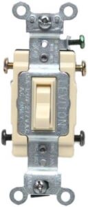
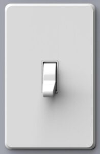
A four-way switch differs in design and wiring from a conventional “single-pole” light switch. Unlike a single-pole switch that clearly indicates “OFF” and “ON” positions on its toggle, a four-way switch doesn’t have those labels or a right-side up. In addition, unlike a standard single-pole switch that has two terminal screws and a ground screw for wire connections, a four-way switch has four terminal screws and a ground screw (thus its name). (A three-way switch, used for turning on lights from two locations, has three terminals plus a ground screw.)
When wiring or replacing an existing four-way light switch, make sure you attach the wires to the right screw terminals on the new switch. Pay attention to the terminal screw colors in the manufacturer’s directions—the placement and colors of terminal screws may vary from one type of four-way switch to another. Also, be aware that some contemporary switches may have holes where you insert the wires instead of securing them to screw terminals, but the fundamental hookups remain the same. The green screw at the bottom of the switch is meant for attaching the ground wire (typically green or bare)—this is essential for maintaining a safe wiring system.
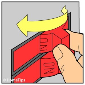
Always turn off the power to the circuit before working with exposed electrical wires. See How to Turn Off Your Home’s Electricity.
How a 4-Way Light Switch Works
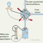
With a standard switch, power is delivered to a light fixture through one white wire and one black wire. A light switch interrupts the black “hot” (charged) wire that connects the power source to the light fixture when the switch is turned off.

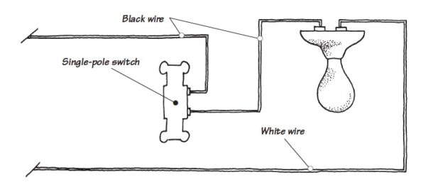
The white wire remains uninterrupted from the power source to the light fixture, and bare grounding wires—also continuous from the light and switch all of the way back to where they’re grounded at the source—are securely fastened to grounding screws for safety. For more, see How to Wire a Standard Light Switch.
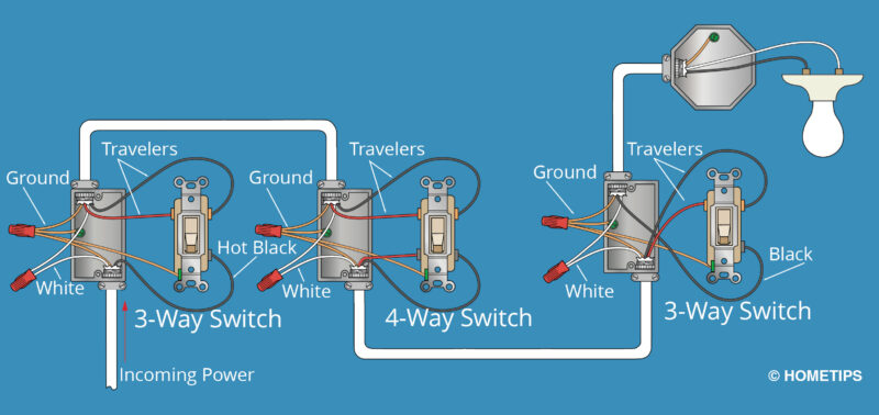
A four-way switch is attached to more wires than a standard switch. Four wires connect the four-way switch to a pair of three-way switches. Pairs of these wires are referred to as “traveler” wires. When any of the switches are turned on, these wires may or may not carry the electrical current, depending on the position of the switches.
Four-way Switch Wiring Diagram
Materials Required for Wiring a 4-Way Switch
To wire a 4-way switch configuration, you’ll need the following components:
One 4-way switch. The centerpiece of the setup, the 4-way switch connects two 3-way switches and allows you to control the lights from multiple locations.
Two 3-way switches. The 3-way switches work in conjunction with the 4-way switch to complete the multi-location lighting circuit.
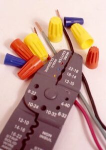
Electrical cable. Electricians commonly use “12-3 with ground” or “14-3 with ground” nonmetallic sheathed electrical cable, such as Romex, to connected switches and lights. This cable includes three insulated wires—white (neutral wire), black (hot wire), and red wire (hot or traveler wire)—and a bare or green ground wire.

Wire connectors. Also called “wire nuts,” these are used to securely connect the wires together.
How to Wire 4-Way Switches, Step by Step
The wiring diagram above provides a visual representation of how the switches and wires are connected. The following instructions assume that the wiring and electrical switch boxes are already roughed-in, and that you just want help with the hookup configuration. For more about the rough wiring, see Home Electrical Wiring and How to Mount a New Electrical Box.
Note in the example shown and discussed here that the 4-way switch is placed between two 3-way switches, and the light is connected to the 3-way switch at the end of the circuit.
Again, be sure to turn off the circuit breaker that supplies electricity to the switches before beginning work. Use a voltage tester to double-check that the power is off before proceeding.
1: Wire the First 3-Way Switch
Using the non-metallic cable coming from the circuit breaker panel, connect the black wire to the first 3-way switch’s terminal as shown in the blue diagram above. For techniques, see How to Cut, Strip, and Join Electrical Wire. Also connect the white wire to the outbound non-metallic cable’s white wire, twisting the stripped ends of the two together and securing with a wire nut. Join all of the bare grounding wires, plus a short “pigtail” grounding wire, using a wire nut or crimp-on copper grounding connector. Secure the pigtail to the green grounding screw on the switch. And then connect the outbound traveler wires to the switch’s terminals.
2: Wire the 4-Way Switch
Connect the wires to the 4-way switch and the second 3-way switch, using the same methods and the configuration shown in the blue diagram above. Also secure the white and ground wires at the second two electrical boxes.
3: Test the Circuit
Carefully tuck the wired switches into their electrical boxes. Turn on the power at the circuit breaker and use a voltage tester to ensure the circuit is powered up.
Do not touch any screw terminals or bare wires at this point! Make sure all the switches turn the lights on and off from each switch.
4: Secure the Switches
Once the wiring is confirmed to be working correctly, turn the power back off. Wrap black electrical tape around the switches’ terminals to prevent future accidental contact with the wires or terminals. Then secure the switches in place with their screws, making sure they are flush with the wall surface.
5: Replace Cover Plates
Finally, install the cover plates over the switches to complete the installation. Make sure the cover plates fit securely and align properly. Then restore the power to the circuit. Now, you can enjoy the convenience of controlling the lights from multiple locations with ease.
Remember to always prioritize safety when working with electrical components and circuits. If you’re unsure about any step, consult a qualified electrician for assistance.
Find an Electrical Pro Near You